
Tajikistan H003 Gas (CO2) Reduction Unit
Category:
TajikistanElectrochemical reduction of carbon dioxide
Product Description
| H003 Gas (CO2) Reduction Unit | |
|---|---|
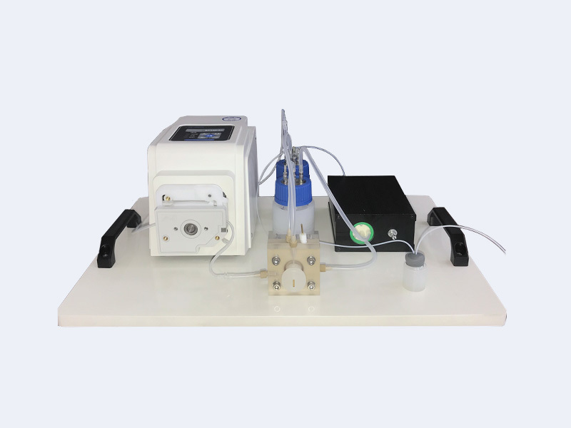
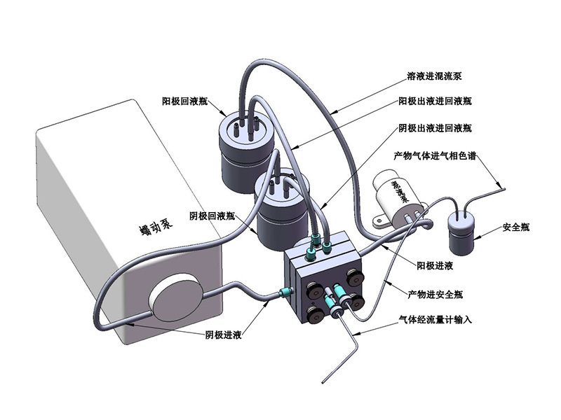
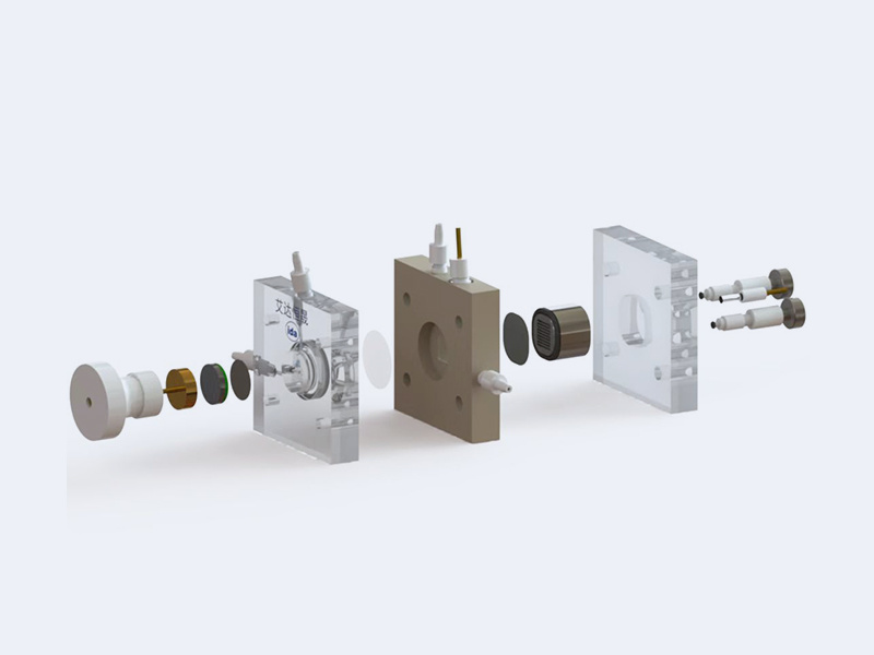
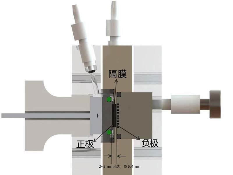
| Uses and Features | 1. The device features a minimum electrode gap of 2 mm (with a separator in between), with options ranging from 2 to 5 mm; by default, it is shipped with a 4-mm gap. This design significantly reduces electrical resistance, eliminating the need for an electrochemical workstation with high cell voltage—standard workstations can readily handle high‑current measurements. 2. The flow channel end is equipped with stainless steel contact electrodes, and the counter electrode employs graphite combined with gold-plated metal components. Compared to the conventional use of copper tape for conductivity, this design significantly enhances electrical stability. The reference electrode is directly inserted into the liquid flow channel, effectively eliminating bubble‑induced interference. The counter electrode may be a metal sheet, a mesh, or a foam structure—none of these configurations compromise the device’s sealing performance. 3. The electrode and separator mounting areas of the device both feature recessed grooves; pre-cut electrodes and separators are individually placed into these grooves, and tightening them ensures both a secure seal and electrical conductivity, thereby enhancing the overall assembly integrity. 4. The device features a simple, user-friendly overall structure that reduces operational uncertainty; this design effectively prevents leakage, poor insulation, or inadequate conductivity. |

Tianjin Ada Hengsheng Technology Development Co., Ltd.


